In 2014 I started with creating my first DIY MIDI controller LambdaControl, which is a channel-oriented MIDI controller that helps operating a Digital Audio Workstation (DAW) like Ableton Live. I started constructing it to support me during my upcoming live performance project, in which I will try to perform my techno-influenced tracks live on stage.
After finishing the first working version of LambdaControl in 2017, I decided to release all material for it under open source licenses, such that others can make us of my work for their own projects. Hence, this page should function as a documentation of the project, in which I try to explain my design decisions, the different parts of the controller and how I assembled them.
In addition to this documentation you can find all the files that I created to build LambdaControl on github. I distributed it into four repositories:
- Hardware repository with for example the button matrix PCB, a vector drawing for the faceplate and the files to create the 3D printable case
- MIOS32 firmware for the MIDIbox core, which is the main brain of the controller
- Matrix MCU Firmware for the separate microcontroller that drives the RGB button matrix
- MIDI Remote Script for Ableton Live that integrates LambdaControl into the DAW
Table of Contents
Introduction
First, I will explain the general concept of my live performance setup and how it influenced the design of LambdaControl. After that I start with building the front panel out of a sheet of acrylic glass. The next chapter will be about the electronics of the controller and why I based it on the MIDIbox project. Following, I explain why and how I build the RGB button matrix and describe its integration into Ableton Live by a custom MIDI remote script. Finally, I show you how I created the case of LambdaControl with my 3D printer, cover the final assembly, and discuss the final result.
Concept
Ableton Push is my tool of choice for improvising during my upcoming live performance, since its interface is very well thought out for exactly this task. However, improvising during the live performance is only possible when controlling the musical foundation (my pre-produced songs) happens without hesitation. Hence, the main goal of this project is to build a controller, which allows me to control the different parts of the songs played during the live performance.
Before I started producing music, I learned to DJ first with Vinyl then CD and in the end Traktor. Maybe this is the reason why I prefer to build my live performance setup also based on the idea of two decks, such that I am able to control two different songs at the same time. Therefore, I need to build two LambdaControl MIDI controllers to have the perfect separation between the two songs.
I also really like the idea of treating the MIDI controllers more like an instrument. Hence, assigning different functions to the same button is not an option, because it makes it difficult to play the controllers without to much thinking. So each controller needs to have a lot of inputs, such that there is no need to assign several functions to the some button.
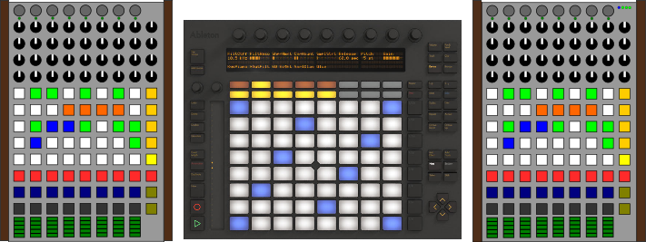
Finally, this means that my current plan is to use one Ableton Push and two LambdaControl MIDI controllers.
Design
The basic shape of the controller is directly defined by the channel based concept of Ableton Live. Every audio track has its own channel with a volume control, a clip launcher to switch between the different sections of the songs and knobs for different audio effects.
Every song played in the live performance will be divided into nine tracks/channels like kick, bassline, percussions, main lead, pads or effects. The final grouping I will figure out when the first version of the live performance setup is finished.
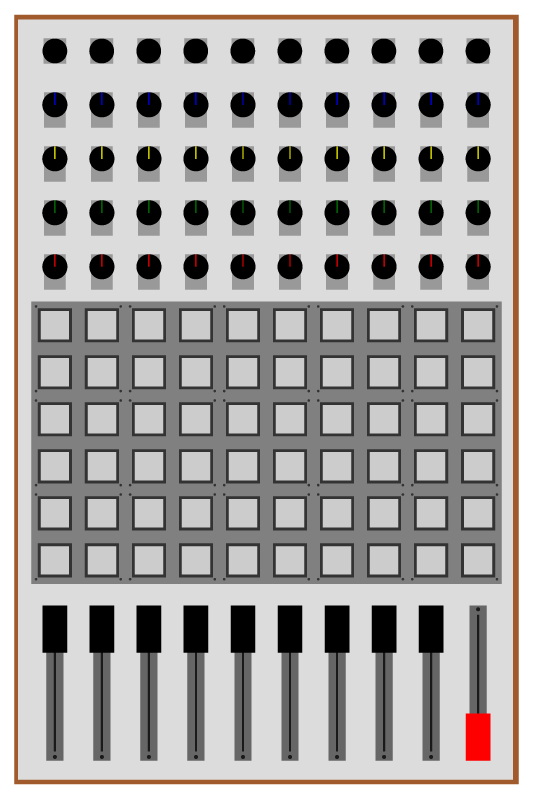
Based on this requirements I designed the following draft.
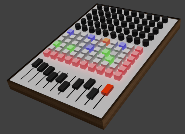
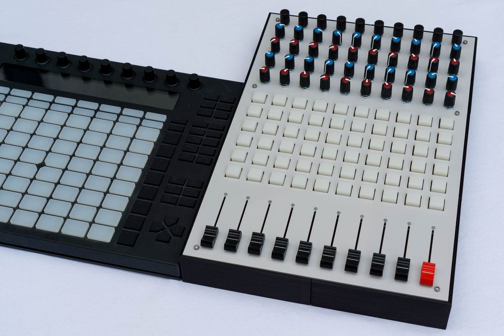
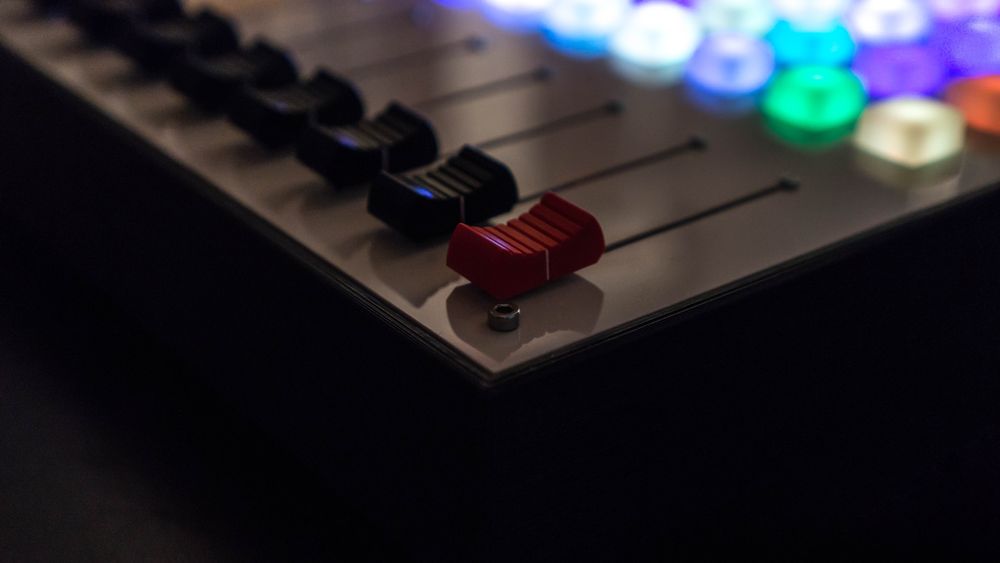
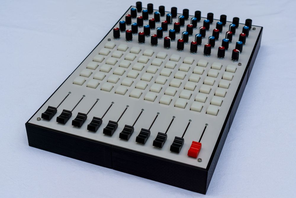
The controller consists of ten channels where the last one is the master channel to control the complete song. Every channel has a line fader to control the volume, six buttons to launch and stop clips, four rotary potentiometers to control the audio effects, and an encoder with push button functionality which allows for example to control a looping mechanism.
Front Panel
After choosing the actual components for the faders, knobs and buttons, it was time to design the front panel. Therefore, I first draw a sketch in Inkscape. After the components have arrived I could measure them and use their actual dimensions for the drawing. In the following sketch you can see the different components with their space requirement behind the front panel (gray parts). Taking this additional space behind the front panel into account is very important, since only then everything will fit in the end. I also created a small paper prototype to check that each component can be accessed easily.
Manufacturing
As material for the front panel I decided to use gray acrylic glass with 3mm thickness. Luckily, I was able to use the laser cutter at the Fab Lab Aachen, which allowed me to produce the front panel with a high precision. Moreover, I could directly use my Inkscape drawing as tool path for the laser cutter. The following video shows the laser cutting process at the Fab Lab.
Having access to an industrial grade laser cutter was really great, since the produced result is far better than anything I could have created by hand. Here you can see the final result.
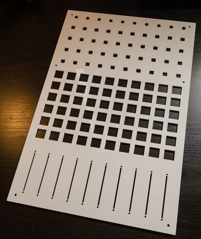
Front Panel Assembly
After the laser cutting, I assembled the front panel by inserting the components at the desired positions. Sadly, the metal shaft of the ordered potentiometers were a little bit shorter than excepted, such that I needed to use a file to carve out the acrylic to have enough space to secure them onto the faceplate by a nut.
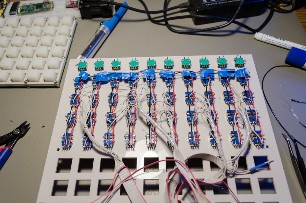
Finally, I planed the cable management for the components. I decided to create the connections by simply using wires, since I thought that creating a dedicated PCB would have been an overkill. Now, after having done all the wiring by hand I maybe would decide differently. At least I could save a lot of connections by connecting the source and ground lanes by a large bus wire instead of using separate wires.
Electronics
Now let us talk about the actual electronics of LambdaControl. First, we will take a look at the MIDIbox project. Secondly, I show how I connected the basic inputs like linear potentiometers, rotary potentiometers, and encoders by using components from the MIDIbox project. The last parts focuses on my custom developed RGB button matrix.
MIDIbox Project
The MIDIbox project is an open source project started by Thorsten Klose that allows you to easily create MIDI interfaces. The project provides the necessary hardware, operating system and software for this. The MIDIbox project provides several different solutions, but for LambdaControl I used a MIDIbox core and several extensions modules, which can be connected to it.
The latest MIDIbox core is build around a buyable development board that uses a 32 bit ARM processor (STM32F407VG) clocked at 168 MHz. The MIDIbox PCB extends this development board with useful I/O. The operating system MIOS32 is based on FreeRTOS and you can either chose to use one of their provided firmwares like MIDIbox NG to program your controller by specifications inside a configuration file or you can freely program it in C or C++ by creating custom firmwares for the MIOS32 OS. You can find more information about this and complete examples on their website.
I decided to use the MIDIbox project as base for my controller, since it provides a complete solution, but still can be extended by custom code and hardware. Hence, I saved a lot of time utilizing from it while loosing no flexibility. Also their hardware solutions are heavily used by people, such that it should be quite stable. Moreover, there is a really nice community on their forum that can help you when you are facing a challenging problem.
Analog Inputs
The analog inputs of LambdaControl are the linear and rotary potentiometers. LambdaControl consists of 60 rotary pots and ten linear ones, such that just using the internal A/D converter of the STM32F4-DISCOVERY board would require to implement a multiplexing to connect so much inputs. Luckily, the MIDIbox project already provides a complete solution for this the AINSER64 extension module. The AINSER board contains a high quality A/D converter (it has a lower noise floor than the internal one) and eight multiplexers, such that up to 64 instead of one analog input can be converted. Moreover, the MIOS32 operating system directly implements the multiplexing for the analog inputs, such that you can just receive the position changes inside your firmware without additional coding.
Encoders
Encoders are endless knobs that send out incremental updates for each step instead of having an absolute analog resistance value. These incremental outputs of an encoder are digital, such that I can make use of the DIN modules to scan a lot of encoders with a small amount of input pins. The DINx4 module basically consists of four 8-bit shift registers, such that it extends the amount of available input pins by 32. You can even cascade the DIN modules to scan even more digital inputs. Moreover, MIOS32 directly implements handlers that listen for changes to the different digital inputs like encoders, such that I can easily send out MIDI messages for them.
Additionally, I decided to use encoders with push button functionality. Hence, you can also use them as normal buttons by simply pressing them down. Therefore, the encoder simply contains two more pins for the button. These can simply be scanned with the help of the DIN modules to detect the button press.
RGB Button Matrix
A big part of the project was the design, creation, and implementation of the RGB button matrix. It is a collection of 60 buttons arranged in a matrix with ten columns and six rows. I decided to go with silicone rubber buttons that establish a button connection by an attached conducting material and a PCB with matching contact pads. Therefore, the button matrix works like the button pad of most TV remotes. Each of the silicon based buttons is hollow, such that it can be illuminated with a common 5mm RGB LED.
Luckily, Sparkfun produces nice silicon pads designed exactly for this purpose. Hence, I based my design around these pads.
In the following I will describes the importance of multiplexing and show the schematic and PCB that I have created. Also, I will describe the actual hard- and software which drives the LEDs and scans the buttons.
Multiplexing
A RGB LED consists of a red, green, and blue LED in a common case which either share the same anode or cathode. Hence, an RGB LED has four pins. Connecting all 60 RGB LEDs of the matrix directly to the microcontroller unit (MCU) is not a good idea, since this would require 180 output pins and around 1.2 ampere when all LEDs are on (the selected RGB LEDs can consume up to 20mA each). Therefore, connecting the LEDs in a LED matrix configuration is a smarter solution. By that I only need 28 output pins and use at max 0.12 ampere when driving just one column of the 6x10 matrix at the same time. The reduction of the needed current is especially good, since the amount of current that can be consumed safely from a USB 2.0 port is with 0.5 ampere limited.
However, driving the LEDs with a matrix configuration is a little bit more complicated. Since, I am lighting up just on column at the same time, I need to iterate over the different matrix columns quickly to create the illusion that all LEDs are on at once and not just one column.
Moreover, 28 pins are not free on the microcontroller s.t. using DIN and DOUT modules to extend the I/O and connect the different parts of the matrix is still necessary. Hence, I need to first feed the data into the shift registers and then trigger the latch before the data is set at the matrix column and rows. This deserialization is generally not a problem, but consumes additional time that needs to be taken into account.
Not only the RGB LEDs are connected in a matrix configuration, also the 60 input buttons are connected by utilizing a matrix. More in depth information about LED and button matrices can be easily found on the Internet.
PCB
Sparkfun also offers a small 4x4 PCB for the silicon pads, but I quickly decided to create my own, since I used an unusual matrix dimension (6x10 instead of the typical 8x8). Moreover, I thought that I could create a nicer layout for my specific purpose and components. Also using one big PCB instead of several small ones results in a overall more stable construction.
Generally, the PCB is created by using a standard matrix layout and consists of contact pads for the buttons, RGB LEDs, diodes, a column selection, and a row selections. The diodes are used to avoid masking errors with the buttons of the matrix, such that no button press is hidden by another one.
I designed the PCB in Eagle and could really benefit from the open approach of Sparkfun, since they license all their parts under open source licenses. Hence, I could reuse the contact pads and measurements of their PCB. Actually, my PCB consists of two separate matrices one for the button input and one for the RGB buttons. However, I placed the column selection pins for the two matrices on one header, such that by soldering the pins together it is possible to drive the PCB with just one shared column selection. In this case the diode orientation and the chosen RGB LED type (common anode or cathode) need to match. Routing the two layered PCB was really a challenge for me, since each of the 60 RGB buttons needs four connections for the RGB LED and two for the button pad. The following shows the final layout of the button matrix PCB.
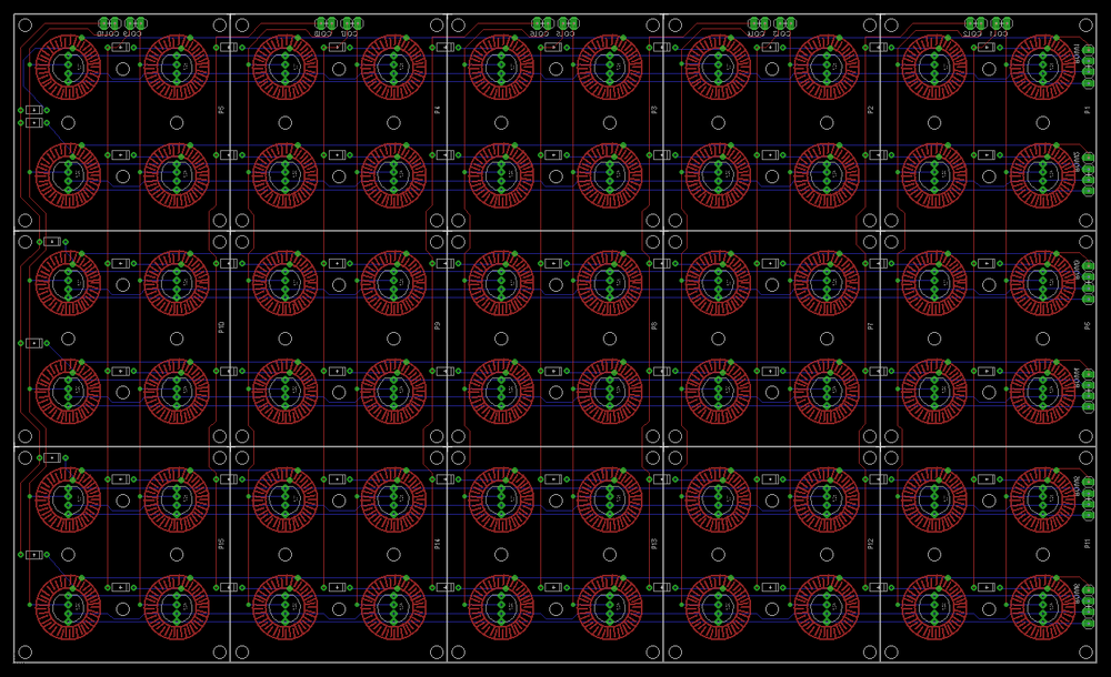
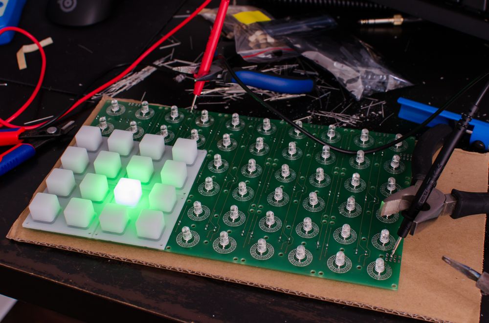
I sent this design to a professional PCB manufacturer and received after some days the following PCB.
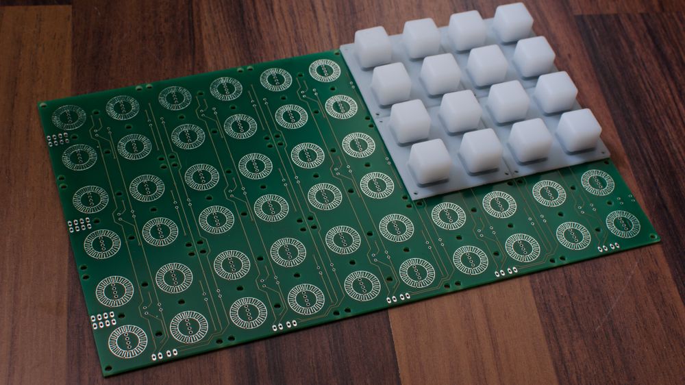
After the arrival, I quickly soldered the diodes and RGB LEDs to the PCB and connected my multimeter in diode test mode to check that everything is working correctly.
Matrix MCU
The matrix microcontroller unit (matrix MCU) operates the button matrix PCB by scanning the button matrix and driving the RGB LED matrix. First, I explain why I added a second MCU to drive the matrix. Second, I show how the MCU creates a lot of different colors by using Bit Angle Modulation (BAM) without using a lot of processing power. The final section covers the communication between the MIDIbox core and the matrix MCU via I2C.
Reasons for a separate MCU
Driving the button matrix PCB was the greatest challenge of this project. The MIDIbox project provides with the MIDIbox NG software a nice overall solution for DIY MIDI controllers that also allows to scan a button matrix and drive a RGB matrix. However, I tried this variant and decided to drive the PCB by custom code, since the amount of available colors is currently limited inside MIDIbox NG. For my use case the amount of available colors is really important, since LambdaControl’s clip matrix should behave like the clip launcher of Ableton Push, which is not possible with only 16 colors. Especially, the unusual matrix dimension of LambdaControl conflicted with the approach of MIDIbox NG, since the amount of available colors is bound to the size of the matrix and a 6x10 matrix needs to be driven like a 16x16 matrix, which again limits the amount of colors.
With a custom implementation for the button scanning and driving of the RGB LEDs, I could solve these problems and achieving a high amount of different colors for the clip matrix.
First, I tried to drive the matrix by just using the MIDIbox core with a custom firmware, but this approach was for me not successful. The main reason for this was that the LEDs on the matrix quickly started to flicker when the MIDIbox core was busy with other tasks. Even after several iterations I could not solve this problem and achieve stable timings.
LambdaTon from the future here: Later after I have finished the controller and shared it with the community, Thorsten Klose, the creator of the MIDIbox project, pointed out that in general there should be no problem to implement a RGB matrix like mine with just using the MIDIbox core. Hence, if you want to invest some time this should also be an option.
However, I decided to take a short cut and implement the matrix related tasks on a separate microcontroller unit (MCU) to decouple the several tasks physically and achieve a more consistent timing without digging deep into the MIOS32 and FreeRTOS code. The connection between the MIDIbox core and the added matrix MCU is achieved by I2C.
Another option would have been to use one of the many existing RGB LED matrix driver ICs out there, but I found the challenge of implementing all in software really interesting. Maybe, I will use one of them in a following project.
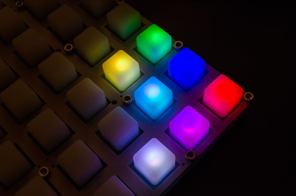
Matrix Colors
With RGB LEDs we can create seven colors by simply combining the different LED colors red, green, and blue. The color mixing with these light emitting diodes is additive, such that we produce white when the red, green, and blue LEDs are turned on. The following picture shows these seven base colors.
Pulse Width Modulation (PWM)
However, seven colors are not enough for my purpose. Hence, I need to generate more colors by driving the three LEDs with different intensities (for example 50% of full power). This intensity control can be implemented by using a pulse width modulation (PWM). The PWM signal is a square wave signal (either completely on or off) and has a specific frequency at which this on and off period changes happen. A PWM signal with a 50% duty cycle is half the time on and half the time off. In my LED case this means that the LED with a 50% duty-cycle PWM is driven with half the power. Our eyes do not recognize brightness linearly, such that this does not mean that the LED driven with a 50% PWM signal looks half as bright as the full powered LED. However, for just creating different colors for the RGB button pads, learning more about this is not necessary. Finding nice colors by experimenting with the different settings is the simplest solution.
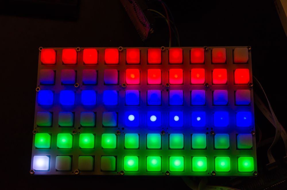
The PWM allows to control the intensity of the different LED base colors, such that combining the different intensity combinations allows to create a lot of different colors. The following picture shows the 16 intensity values (goes up from right to left and each base color is shown in two rows) that I use with LambdaControl.
Problems with Software PWM
If I want to drive the RGB LED matrix with 120 Hz, this means that I need to set the complete matrix with its ten columns every 8.33 ms. So, I have 0.833 ms to set the color in one column. If I want to provide 16 intensity levels for each LED within one of these refresh periods, I need to split the 833 µs into sub-chunks for the PWM of 52 µs length. In a simple software PWM implementation this means that I need to fire in one seconds 19200 interrupts and turn the LED either on or off in each one depending on the desired color.
So, in my scenario a software based PWM implementation is quite computing intensive for the small microcontroller that I have chosen. Especially, since it still needs to change the multiplexing, feed the data into the shift registers and communicate with the MIDIbox core. Hence, using the more efficient Bit Angle Modulation (BAM) is a good decision in the given scenario to reduce the number of necessary interrupts.
Bit Angle Modulation (BAM)
Luckily, our eyes and brains are sluggish in regards to very quick brightness changes. Hence, for us humans it does not make a difference if we see a perfectly timed PWM signal with a 50% duty-cycle or any other distribution as long as the overall on/off-ratio stays the same. BAM reduces the amount of necessary interrupts by using a small amount of interrupts with different durations instead of a large amount of interrupts with a fix duration. For example, lets say that the smallest interrupt should consume 52 µs. Then the second interrupt takes 111 µs, the third 222 µs, and the last one 444 µs. All four interrupts together take 833 µs, which results in a driving frequency of around 120 Hz for the ten column matrix. By turning the LED either on or off in these four interrupts, achieving the same 2 to the power of 4 = 16 intensity levels is possible, but with only using 4,800 interrupts in one second. In contrast the classical PWM approach would require 19,200 interrupts in one second. Hence, the microcontroller is less occupied and free to do other stuff like communicating with the MIDIbox core.
Drawbacks of the current Implementation
Driving each matrix column with BAM generates a nice variation of color and saves compute time. However, these BAM routines need to happen quickly to be able to achieve a good refresh rate. By experimenting I were able to produce good results when the BAM interrupts together consume 3.84 ms. This also means that a full refresh of the matrix takes 38.4 ms, which results in a refresh rate of around 26 Hz. This refresh rate is actually quite low, but with the chosen 16 MHz processor and the necessary shift registers artifacts appeared when driving the matrix faster.
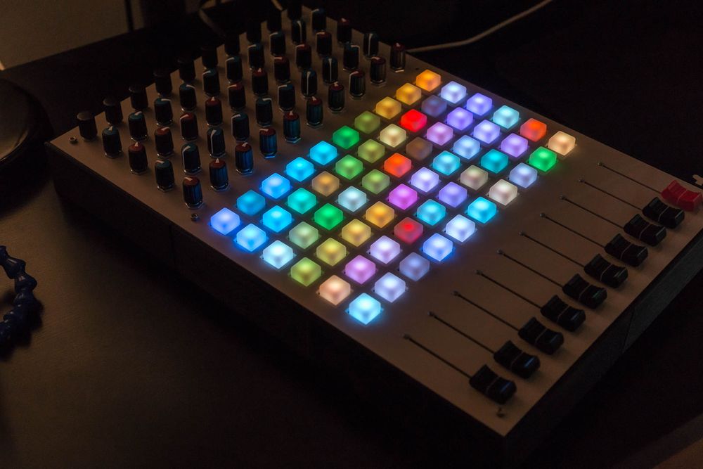
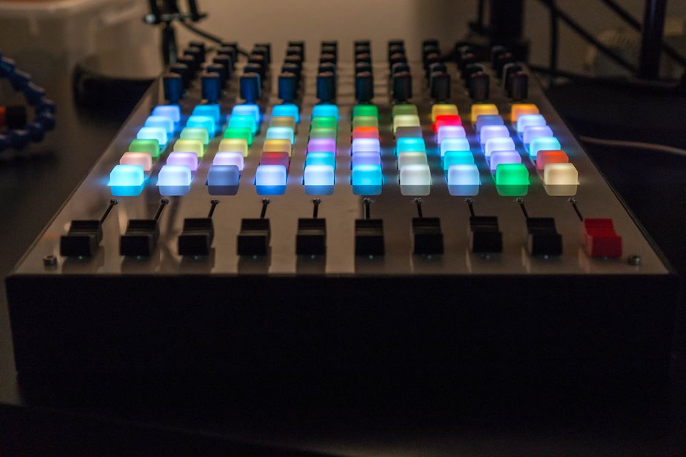
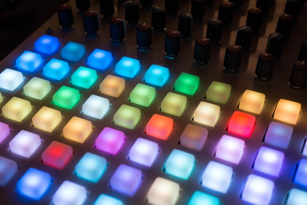
The following picture shows the nice colors that LambdaControl produces by using BAM with multiplexing.
I think that the low refresh rate of the matrix would only be a problem with quickly changing content. But LambdaControl’s grid content does not change that frequently. The clip color is constant during the performance and the content of the matrix only changes when a clip gets triggered/stopped or the clip window is moved. Hence, this limitation is currently not a big problem.
For future projects I will definitely use a specialized IC or FPGA for driving matrices, since they allow to drive the LED matrix with a really high refresh rate without consuming any computation time from the MIDI controller MCU. Moreover, they drive the matrix with stable timings such that flickering should not be a problem.
Here, you can find the complete implementation of the matrix MCU firmware written in C++.
Input Debouncing
Every mechanical button bounces (quick changes between on and off) before a stable state is achieved. Therefore, debouncing the input buttons is an important task. LambdaControl implements this by sending only button change events when the inputs are stable for two complete matrix scanning runs. Each of this runs consume as shown in the previous section 38.4 ms, such that the input delay of LambdaControl is above 76.6 ms and below 115.2 ms depending on the timing of the button press. Additionally, the delay is increased by further processing steps like the I2C communication with the MIDIbox core and the MIDI message transmission over USB.
This delay is to large to play notes with the grid, but for its current use-case of triggering clips this should be fast enough. Techno normally is played at around 128 beats per second, such that I have even in the last bar of a clip 1.875s to trigger the button before the same clips gets replayed. But, a faster button scan rate would be a good improvement and can easily be achieved by using a faster MCU or using a specialized IC to scan the matrix.
Moreover, the debouncing works on column-level and not on button-level, such that only one counter for each column is used instead of six counters for each row. This means that LambdaControl is able to detect multiple button presses, but each new button press inside the same column retriggers the debounce procedure for this column and increases the input delay. This is not a huge drawback, since in the given usage scenario as clip launcher only one button press in a column makes sense. Hence, this is a good optimization, since I only need to store and maintain ten counters for the columns instead of 60 counters for the individual buttons.
I2C Communication
The introduction of the RGB button matrix MCU directly created the need for a reliable communication mechanism between the matrix MCU and the MIDIbox core, such that the MIDIbox core can send the color information to the matrix MCU and the matrix MCU can inform the MIDIbox core about button presses. This interface is implemented by I2C, which is a bus communication protocol that allows to communicate with up to 127 devices. Luckily, the used MIDIbox core directly supports I2C such as the MIOS32 OS.
When the MIDIbox core gets a color change event from Ableton, it directly transmits this event via I2C to the matrix MCU. Moreover, the MIDIbox core frequently polls the matrix MCU for new button presses. When no button press has happen, an empty button event is sent as response. Moreover, the matrix MCU stores the button events inside a ring buffer, such that the button events can be temporarily stored before the transmission. This mechanism works quite well in the given scenario. However, a nice future change could be to implement an external “new button event”-interrupt, such that the MIDIbox core just asks for button events when necessary.
Ableton Live Integration
Currently I am using Ableton Live to produce my music, such that Live will also be used for my live performance. Therefore, LambdaControl needs a complete integration into Ableton Live like Ableton Push. The simplest way to integrate a MIDI controller into Live is by using the MIDI mapping feature. However, the MIDI mapping feature does not provide a way to fully make use of the clip launcher, such that a special script called MIDI remote script is necessary.
MIDI Mapping
Integrating simple controls like the volume fader of a MIDI controller into Ableton Live is easily achievable by using the MIDI mapping feature. You simply click on the MIDI mapping tool icon in Live, select the desired function in the GUI and then use the corresponding fader on the MIDI controller to program the mapping. Therefore, all simple controls like the volume faders or send/return-pots can be programmed by using the MIDI mapping feature. This also has the benefit that changes to the mapping can be easily achieved from Live’s GUI. However, not all features from Live can be mapped by the MIDI mapping, such that LambdaControl also needs a special python script, which Ableton calls MIDI Remote Script.
MIDI Remote Script
As already mentioned, complex tasks like controlling the clip launcher (and getting feedback from it) is officially not supported by Ableton Live for custom controllers like mine. Hence, I need to make us of the so called MIDI Remote Scripts, which Live internally uses to integrate controllers like Ableton Push or the Launchpad. Actually, I got all my information about the MIDI remote scripts from Julien Bayle’s website.
The integration of LambdaControl’s grid into Ableton Live 9 is achieved by a specifically for this purpose written MIDI remote script, which you can find on github. The script tells Live that LambdaControl has a RGB matrix of size 6x10. Moreover, it programs the endless encoder of the master channel as selection method for the grid, such that it can be used to scroll up and down in the clip launcher. For more information check out the website of Julien Bayle or the MIDI remote script repository on github.
Case
My first idea was to create the case for LambdaControl out of wood, but at the end of 2016 I discovered 3D printing as a new hobby, such that I quickly changed my plans and used my 3D printer to create the case. Overall, this creates a better final results, since my wood working skills and tools are limited.
First, I designed the 3D model for the case in Fusion 360 and selected a proper mounting mechanism to connect the different parts to the case. After that I printed LambdaControl’s case with my self-build FDM 3D printer out of PLA plastic.
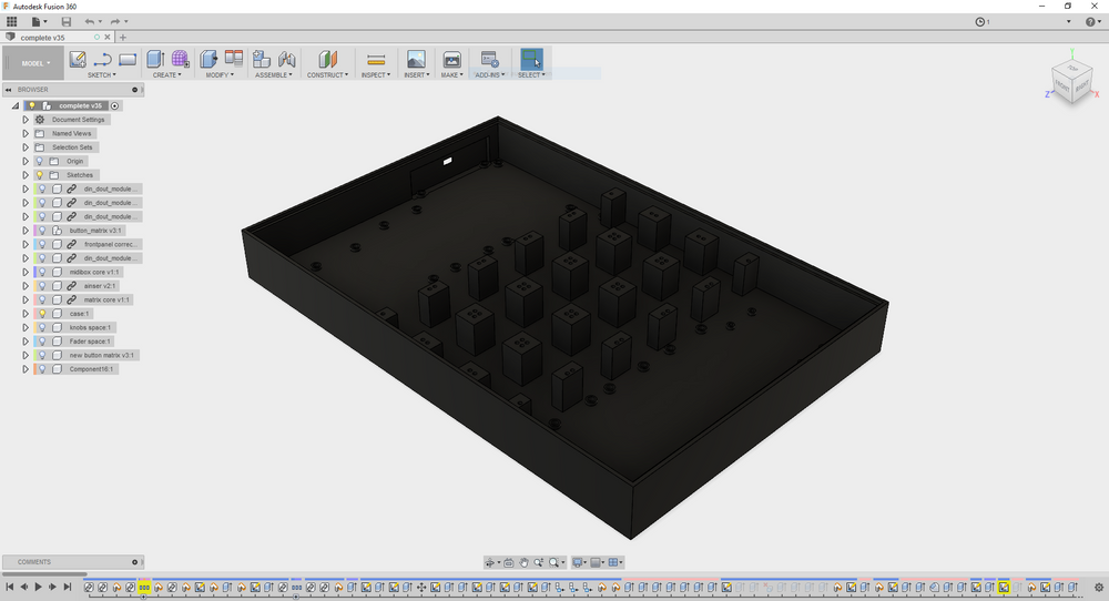
Design with Fusion 360
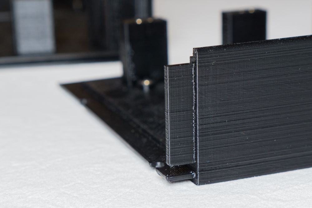
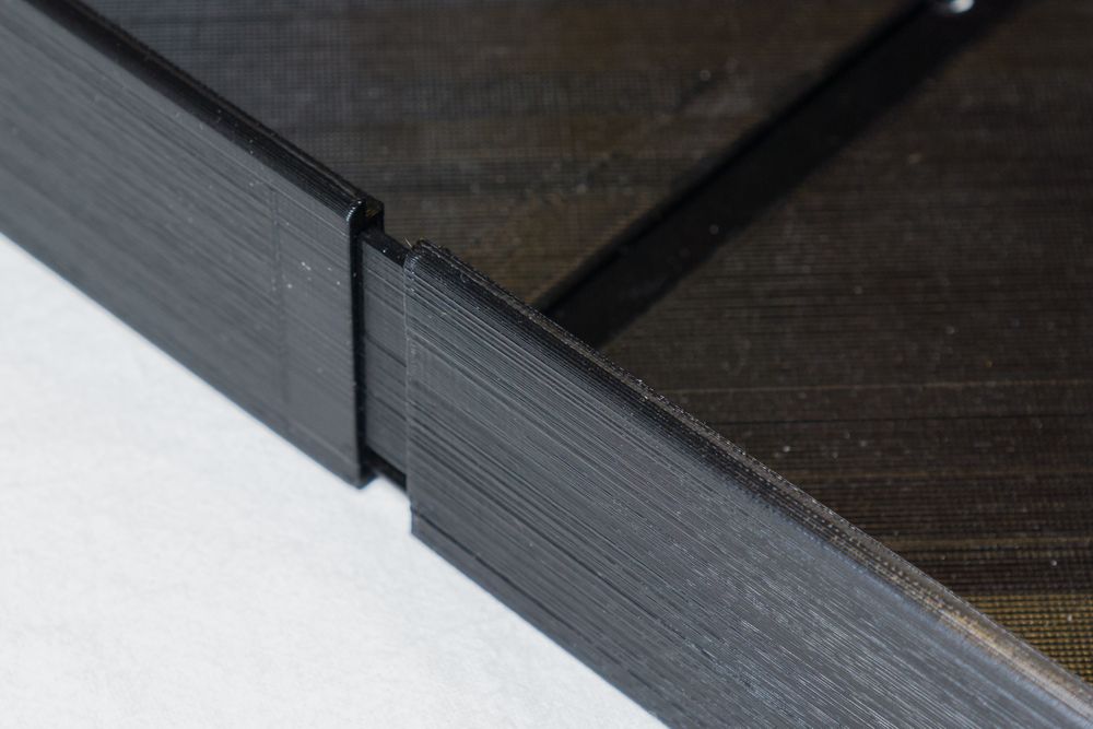
I designed the case in Fusion 360 such that it contains all necessary PCBs and a stable mounting mechanism for the RGB button matrix and the front panel. However, the actual case is with 416.4 mm x 276.4 mm to large to be printable by the current mostly common 3D printers (mine is sadly not an exception to this). Therefore, I split the case into six chunks that are connected to each other by using tongue and groove joints. Hence, the case can be printed by the most common 3D printers out there. All necessary files to print the case can be found in the hardware repository.
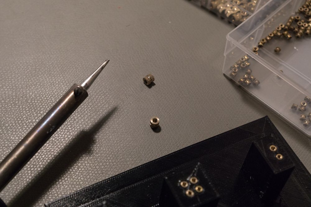
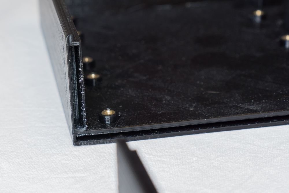
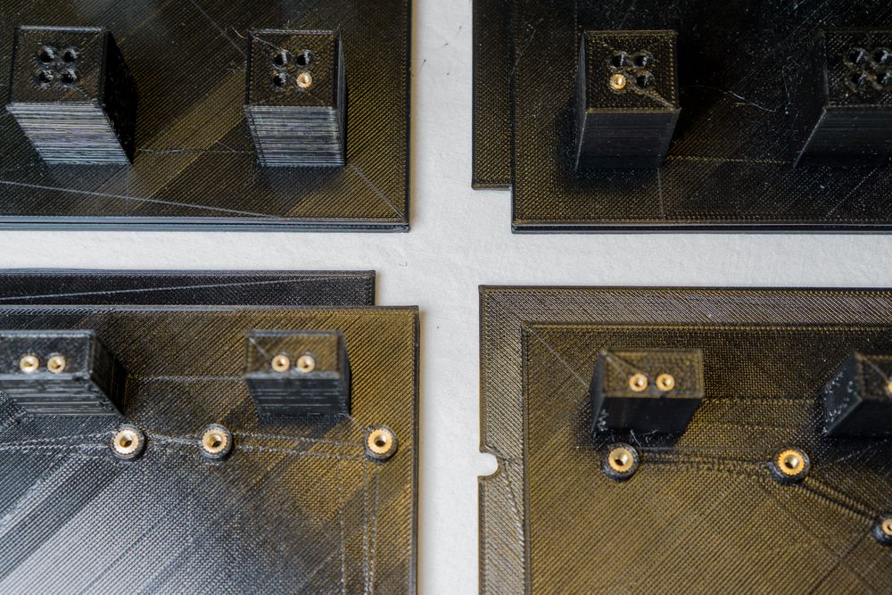
Mounting Parts
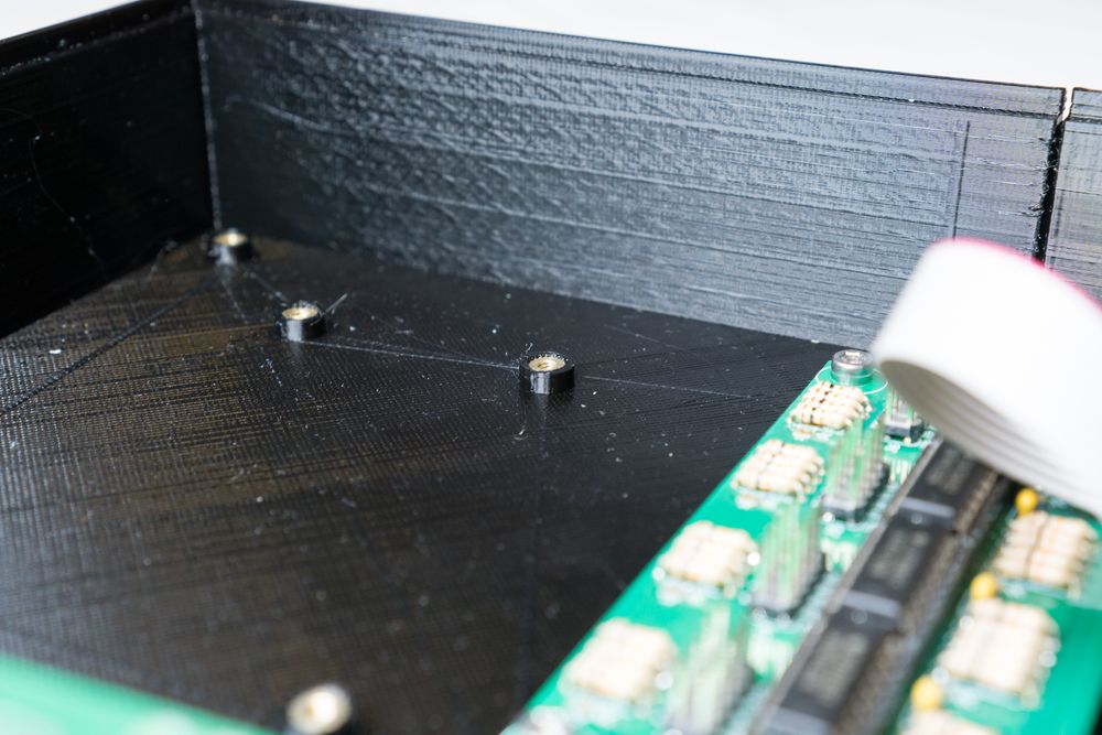
A stable mounting mechanism is necessary to mount the faceplate, PCBs, and RGB button matrix securely to the case. A good option for this are common injection molding inserts. These inserts are made out of brass and are threaded, such that they can be used with standard screws. The modeled case contains for each connection a hole that can be filled with such an injection molding insert. These inserts can easily be pressed into the holes by using a soldering iron with a round tip.
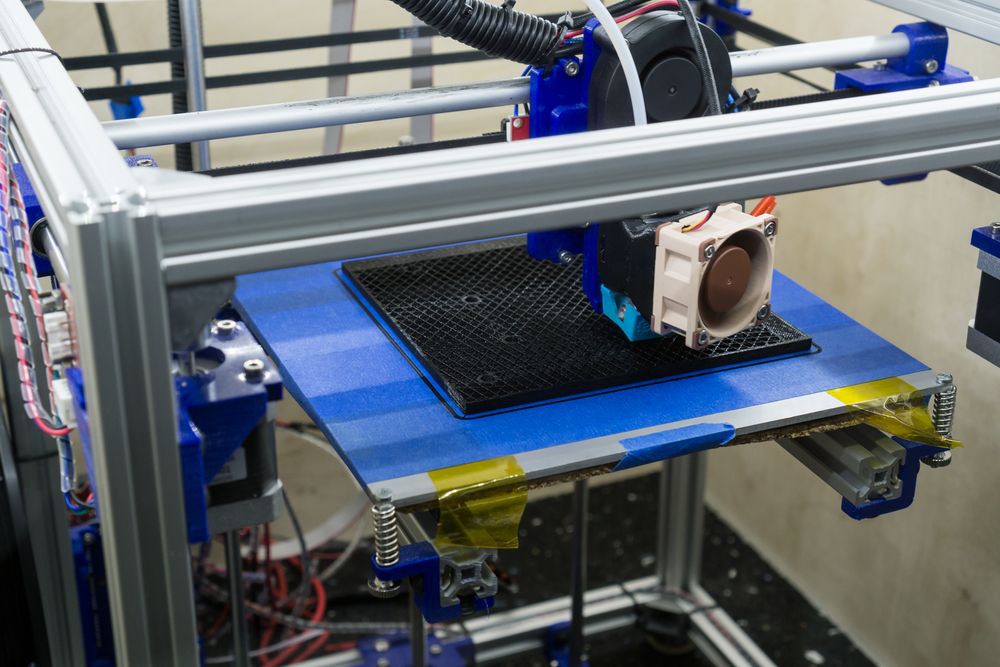
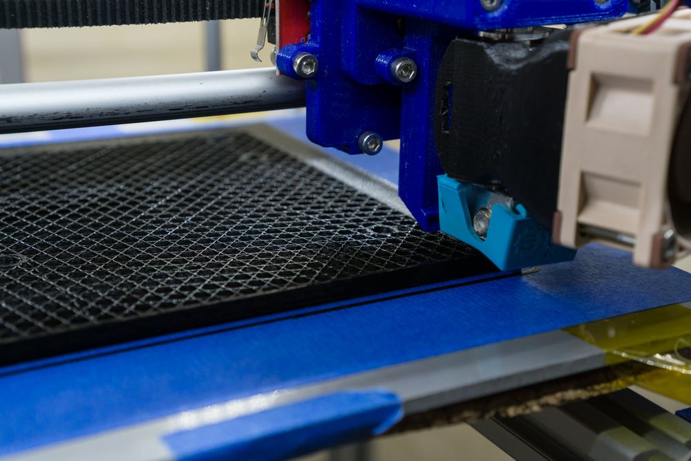
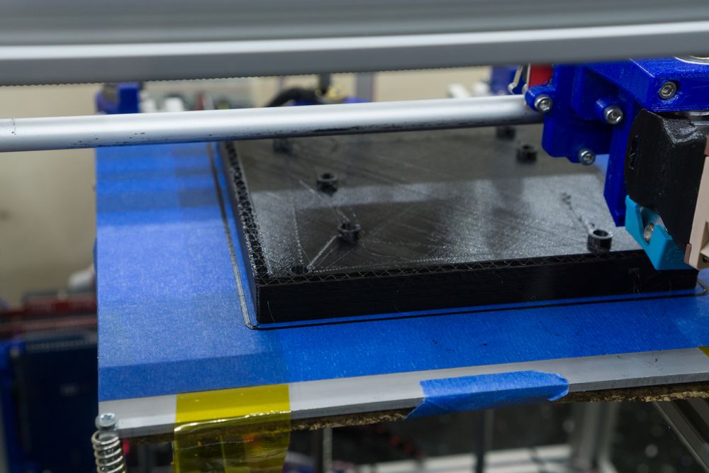
3D Printing
Printing the case parts is relatively easy, since they only require supports in the tongue and groove joint areas. However, printing the parts required on my DIY 3D printer around 13 hours per piece with a 0.2mm layer height. So the complete case required around 78 hours to be printed. The following pictures were taken during the print process.
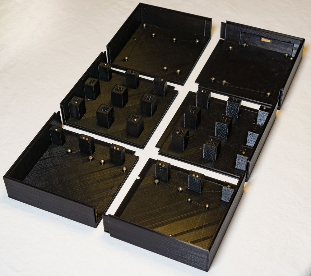
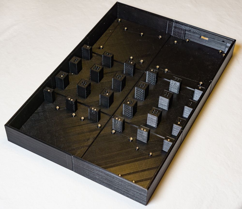
Print Result
The following pictures show the final result. First, you can see the six pieces and how they are arranged to create the complete case. The tongue and groove joints work perfectly and create a secure connection between the different pieces. Special thanks to my friend Henning for the tip with the tongue and groove joints. Overall, I were really happy with the results that my DIY 3D printer produced. But, I think with a little bit more tuning even better results can be achieved.
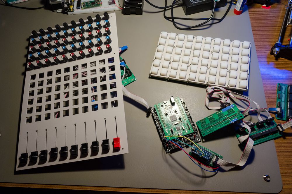
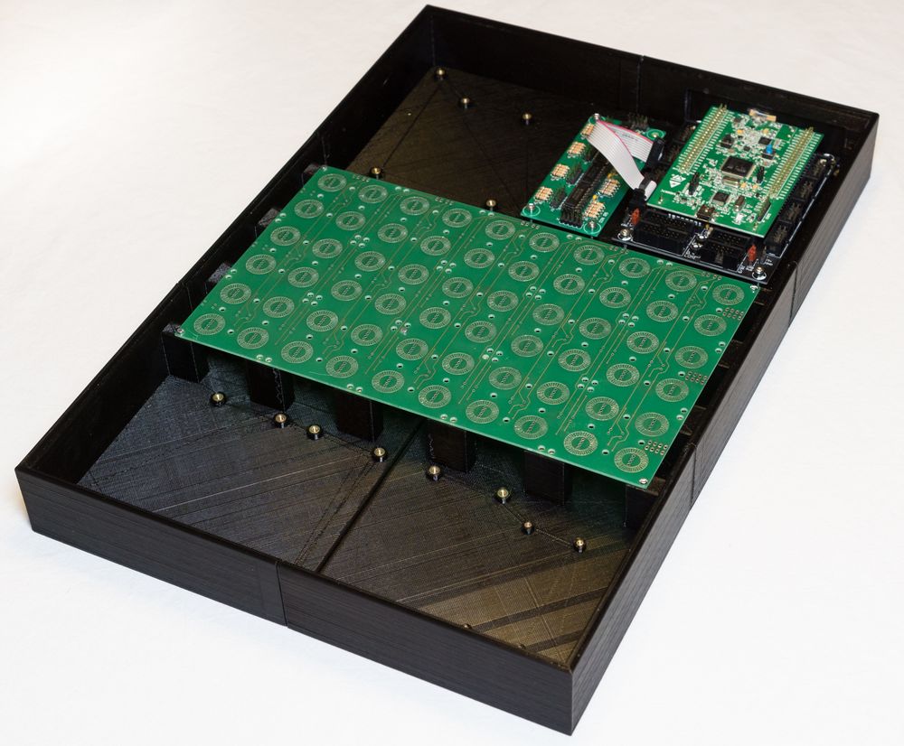
Assembly
Assembling the different parts together was really straight forward after all the work. I simply put the electronics into the case, connected everything, and closed the case with the front panel. Sadly, I have not taken a lot of pictures during this process, because I could not wait to test out the final controller. However, the following pictures should give an impression about the inner workings.
Conclusion
Finally, my DIY MIDI controller LambdaControl is alive and performs as desired. During the creation process I really learned a lot.
If you just want to make music, I strongly advice you to just by a finished MIDI controller and adjust it as far as possible to your needs and accept the compromises you need to make. Since, with a project like this you definitely spend more money and time (of course this highly depends on your skills and available tools). But, I still would jump into this rabbit hole of creating my own DIY controller again without hesitating, because I enjoyed the journey.
So for me, the next chapter of the “creating a live performance”-tale starts with implementing and testing my general concept. And I am really sure that this will not be the last iteration of LambdaControl. Actually, I still need to assemble the second controller…
So, I hope this information will help you to create your dream MIDI controller.